A surf, or .srf file is a multi-use file, used for low detail visuals, collision files, cockpit files, and the building blocks of the visual .dnm files. The structure of the .srf file is used to internally define mesh objects in a DNM file. For completeness, DNM-only elements are included in this breakdown of the SRF file.
File structure[]
The .srf contains a large number of lines with many numbers, each denoting a vertex, or a point in the file. These are then joined into faces later in the code.
Header[]
Each .srf file starts with a line with "SURF"
Vertex Section[]
The first line of the code declares the file is, in fact, a surf file. Below that lies all the vertex information, giving the vertex's position on the X, Y, and Z axes:
V 0.286748 0.958462 5.806995
There is an optional final element to the vertex line that indicates if the vertex has smooth shading applied to it. In this case an "R" will be after the last coordinate input. This R is only applied when the shading on all faces that use the vertex is smooth.
Face Definition[]
The faces that are made from the vertices are defined in 5 or 6 lines (see below for examples of each). Each face definition begins with a line with only a "F" on it and each face definition ends with a line with only an "E" on it. Other than these constraints, the other lines in the face can be defined in any order.
Faces have an ID number which is the order they are defined in, starting with zero and counting upwards.
F
V 25 26 2 1
N 0.153079 0.697158 5.892211 -0.309806 -0 -0.9508
C 127 127 127
E
If the face is to be set as bright, there will be a line in the face definition that is simply "B":
F
V 25 26 6 1
B
N 0.153079 0.697158 5.892211 -0.309806 -0 -0.9508
C 127 127 127
E
| Line Prefix | Line Meaning |
|---|---|
| F | Beginning of a new face definition in the SRF file |
| B | Indicates the face should be treated as a un-shaded light source at night. (OPTIONAL) |
| V | Vertex ID numbers that make up the face. Up to 48 vertices per face has been tested, however legacy tools like Blender 2.49 do not allow for "N-Gon" polygons and thus models created in Blender 2.49 will only export 3 or 4 vertex faces. |
| N | The normal vector of the face. The first three values are the y, z, and x coordinates of the face center. The last three values are the y, z, and x components of the normal vector.
Note that if the Face is double sided, the normal vector components are 0 0 0. |
| C | The RGB color of the face. Each value can be between 0 and 255. 0 0 0 is pitch black and 255 255 255 is pure white. |
| E | End of a face definition in the SRF File |
Once all the faces are defined there will be a line that is only an "E" to end the vertex and Face definition section of the file. In stand-alone .srf files, this constitutes the end of the SRF and anything after it will be ignored.
Internally Defined SRF Meshes In DNM Files[]
DNM Files can have SRFs defined wholly within the .dnm file. The format of the SRF definition is virtually identical with some additional headers used to define in-file references. In addition the end of the SRF definition is extended with 4 different codes to modify the appearance of faces. You can see one example in the code segment below.
PCK Plane.004 16
SURF
V -1 0 1
V 1 0 1
V 1 0 -1
V -1 0 -1
F
C 0 0 255
N 0 0 0 0 1 0
V 0 3 2 1
E
E

ZA 0 50
The first line of the internally defined SRF object will contain the mesh object name, and total number of lines in the definition, including whatever face modifiers are included at the end. Often a little padding is applied between SRF object definitions and the white space between objects is included in this line count.
DNM Internally-Defined SRF Face Modifiers[]
The codes will appear in the SRF section in the order they appear in the list. GF lines first, followed by ZA, ZL and finally ZZ lines. These modifiers will only appear if a face has one of them applied.
| Code | Format | Meaning |
|---|---|---|
| GF | GF GROUPID FACEID ... Up to 32 face ids per line | Group faces - effect TBD |
| ZA | ZA FACEID VALUE FACEID VALUE... Up to 10 face / value elements per line. | The transparency or Alpha of a face (0=opaque/255=clear). |
| ZL | ZL FACEID FACEID FACEID ... Up to 10 face ids per line. | Sets the face as a light source and makes little round lights appear in-game. |
| ZZ | FACEID FACEID FACEID | Hides faces in CPU-rendered executable from 2012 and earlier (no current function) |
Differences between Bright and ZL definitions[]
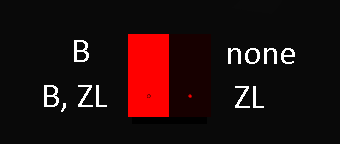
ZL vs Bright in YSFlight as rendered by Direct3D (D3D)
As you an see from the images to the right, there Bright and ZL are not the same thing. With Bright, the face is simply made a light source with the same shape and color of the mesh defined in the SRF.
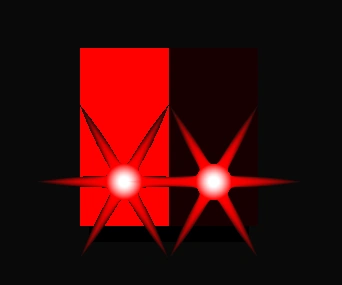
ZL vs Bright modifiers as rendered by YSFlight in OpenGL2 (OGL2)
When the ZL tag is applied to the face, the mesh center has a 2D light sprite applied to it. In Direct 3D (D3D) and OpenGL1 YSFlight this sprite is a 4x4 pixel circle at all ranges, however in OpenGL2 (OGL2) YSFlight rendering the sprite, a white circle with six diffraction spikes, gets smaller with increasing distance.
The ZL sprite is the same colour as the parent face, and visible from the same normal. In OGL1 and OGL2, sprite occlusion is calculated (where nearer sprites always block farther sprites if they overlap), but D3D renders overlapping sprites randomly.
Stock aircraft use the ZL modifier to make SRF objects appear as navigation, beacon or strobe lights as it is a simple way to create a nice looking light.